
An rCOS walk-through.
In this article we explain how to reproduce the CoCoME example model in the rCOS Modeler. If you feel lost, there is a cheat sheet at the end. As a convention, UML model elements are written in CAPS.
Where to begin?
Create a new rCOS project
After starting the modeler, use the dialog, and give the project a name. Create a new model with File->New->rCOS Diagram in this project. Pick a model name, and keep the other dialog defaults, i.e., start with an rCOS Use Case Diagram. The system may ask you to switch to the Topcased Perspective, which is exactly what we want.
Modeling a Use Case
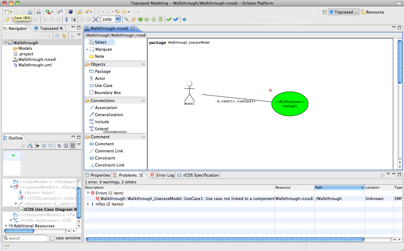
A use case diagram contains Use Cases (surprise!), Actors, and Associations between them. In the new diagram, create an Actor and a Use Case using the palette. Now click the green checkmark-button at the top for the model validation. You will see markers on your elements—go to the Problems tab to see them in more detail. If you have exactly followed the tutorial, you should have one error and two warnings:
Use case not linked to a component
Actor is not associated to any use case
Use case is not (directly) linked to any actor
The component will be automatically created once we proceed. The two warnings are the inverse of each other, and we fix them by drawing an association between the Actor and the Use Case. Run the validation again, and the warnings disappear. (Implementation note: we mostly use OCL rules to validate the model. There may also be other validators that contribute markers.)
A note on deleting elements: if you make a mistake and would like to delete an element, the tool reminds you that there is of course a difference between deleting something just from a diagram (it will still stay in the model as you can verify through the Outline), or from the model (which will also remove all references to the element and may leave you with an incomplete model). Now, right-click on the use case and select Open component diagram. This takes you to the component diagram.
Component Diagrams
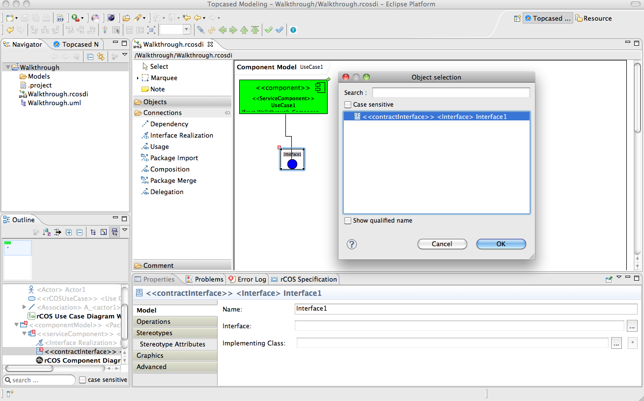
By default, you get one Component per Use Case. The component needs a Contract Interface which specifies its operations. Note that Contract Interfaces are different from plain UML Interfaces—you will not be able to connect a plain interface to a component! So add a Contract Interface, and link it to the Component with an Interface Realization. Run the model validation again.
Contracts and Syntactic Interfaces
A contract interface must have a syntactic interface. As in rCOS contracts can in principle be modelled on different levels, the syntactic interface only describes signatures. In this way, other elements like the contract interfaces can refer to this syntactic interface as a template, and override/refine the contracts which are stored in the body of operations.
The validation now reminds you that the syntactic interface is missing. We could add a plain interface to the diagram, and then configure it in the Properties of the contract interface. Here in our small sample model, we can use a trick: we let the syntactic interface refer to itself (since it is a stereotyped interface)! In Properties/Interface, select the interface itself. Voila, model validation is now happy.
Datatypes
Before you can do anything useful in the modeler, like creating the contract, we need to add any datatypes that our model uses, in the form of a class diagram. We get there through a context-menu on the component diagram, Open class diagram.
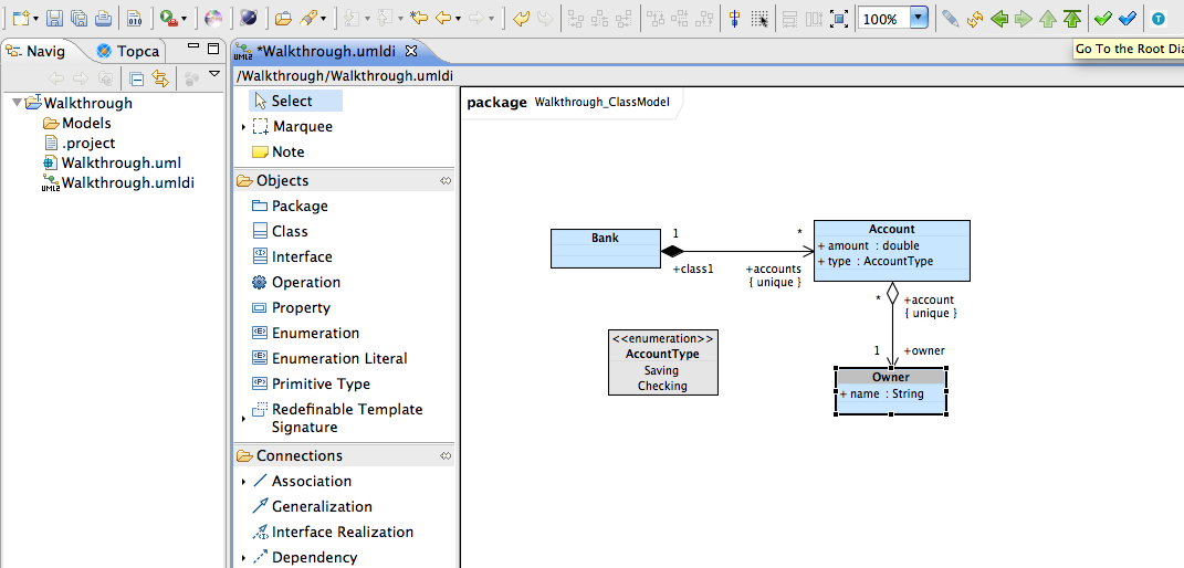
Use the class diagram editor to define your data-model. Remember to use the Properties-tab to edit finer details like multiplicities, and types of attributes (called Properties in the palette). Note that as usual, the modeler will not let you use certain UML elements by default, e.g. Association Classes are not available from the palette, because the modeler only knows how to manipulate a subset of UML in the other stages.
In the rCOS methodology, we'd like you to only define datatypes, and no operations yet! So just attributes of primitive types and associations, please :-) Let's do a simple Banking-example:
Use the green arrows at the top-right to quickly navigate back to the component diagram, or double-click on the component diagram in the outline view.
Protocols
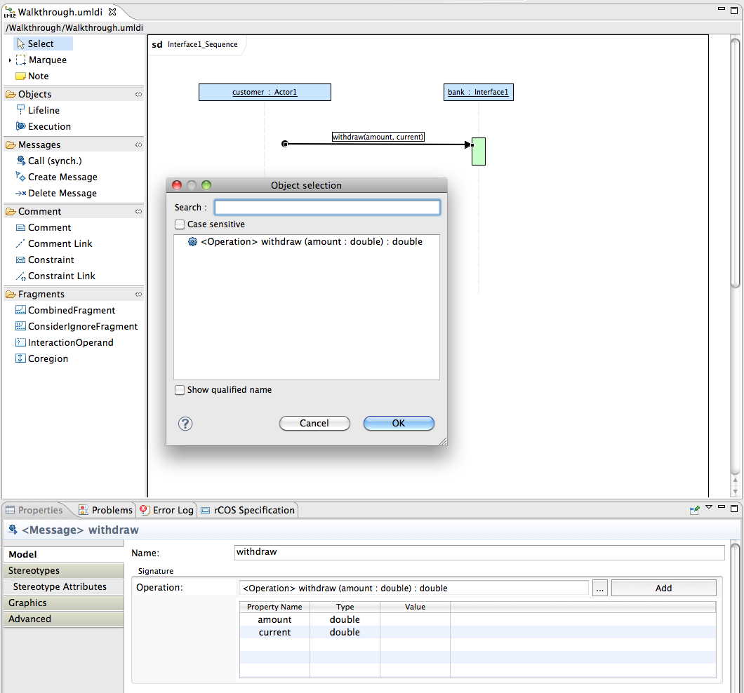
If you look through the warnings on the model, you note that our contract interface does not have a protocol, i.e. a dynamic behaviour specification. These can be given in the form of a state machine, or a sequence diagram. Right-click on the contract interface, and create a sequence diagram. In the subsequent editor, create two lifelines, and use the Properties-tab to let one "represent" the actor, and the other one the contract interface.
Draw a "Call" message from the actor- to the contract-lifeline (this can be a bit tricky!). For the new message, we now need to create a corresponding operation. The corresponding dialog is a bit difficult to use! In the Properties tab, click on the "Add" button. A new operation with a fresh name will be generated, e.g. "Operation1". In the middle of the dialog, you can change the name; here, we would like to "withdraw" money.
Parameters are added in a similar manner: first, press the "Add" button, and then edit the generated new parameter. We would like to withdraw some "amount" of type "double". In addition, we would like a parameter with direction "return" of the same type which might carry information about how much money is left in the account. Finalize creating the new operation by selecting "Done", and then use the "..." button to select the operation:
Cheat-sheet
Some notes on trouble-shooting:
If you think you are missing tabs or windows, make sure you are in the TOPCASED perspective. If you are not sure, use , and/or .
Keep an eye on the Error Log tab (it should be in the same are as the Properties tab. If it is missing, use or reset the perspective (see above).